When +12VDC....Isn't or Why to avoid cheap wall warts
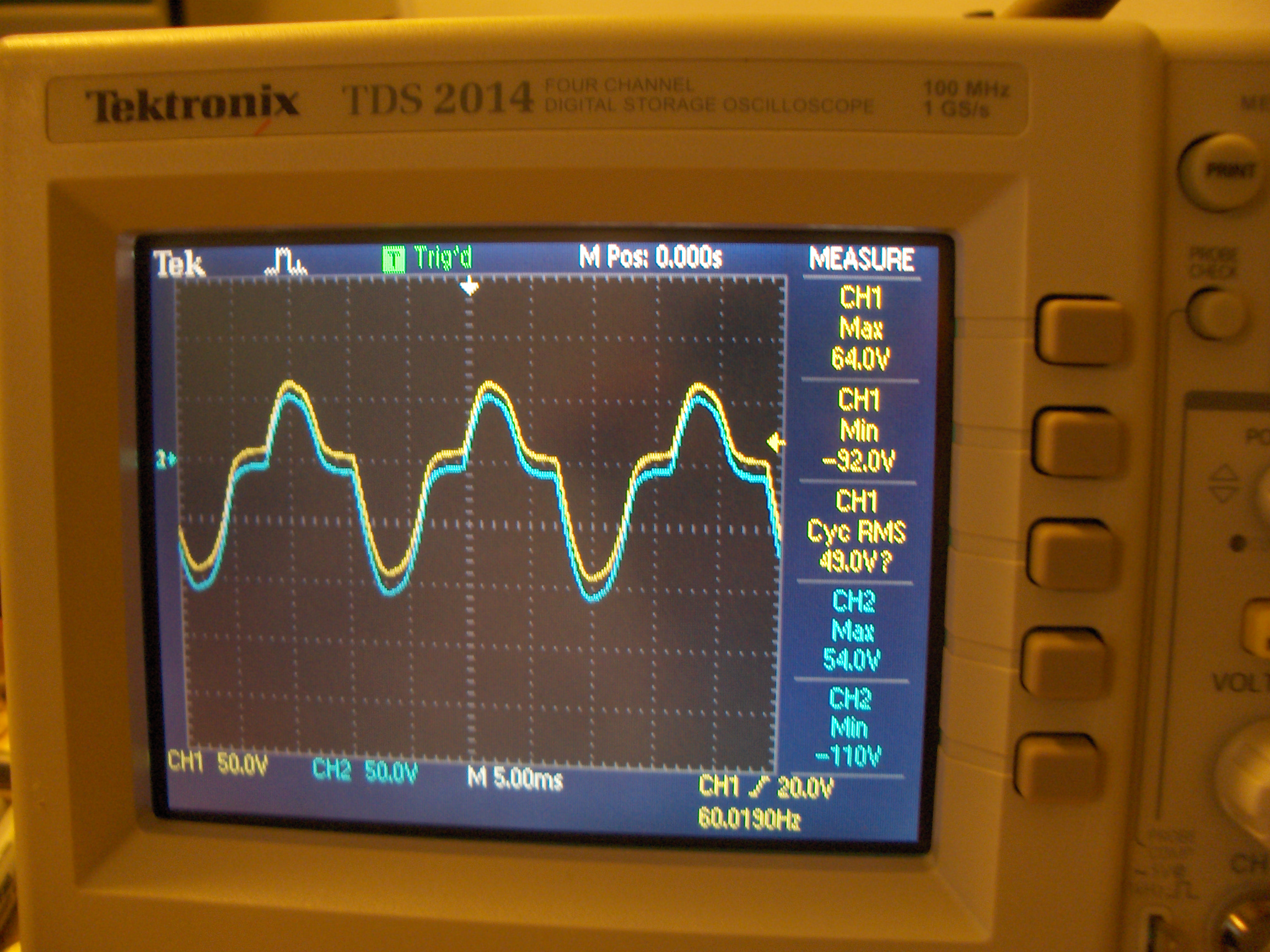
First excuse the err…crude “Screen Shots” – I don’t have my ‘scope setup yet for proper screen captures so I just took pictures.
For a while now I’ve had a +12VDC wall wart that I use occasionally. It always caused weird heating though in regulators. I was never sure why, the multi-meter read it as having a fairly stable +12VDC. I finally hooked it up to an oscilloscope today…well now atleast I know why…
It’s supposed to be producing +12VDC, center positive. What you’re looking at is the center pin (tip) on the yellow (CH1) channel, and the ring (or barrel) on CH2. The trigger is on CH1 @ the rising edge of the wave at 20V. As you can see it’s getting voltages as high as +65V and as low as -110V. It follows the AC line perfectly, the cycle time measured by the scope almost exactly matches that of the AC line. In fact if I trigger on the AC line (this scope can trigger from it’s AC line input) the waveform stays completely steady.
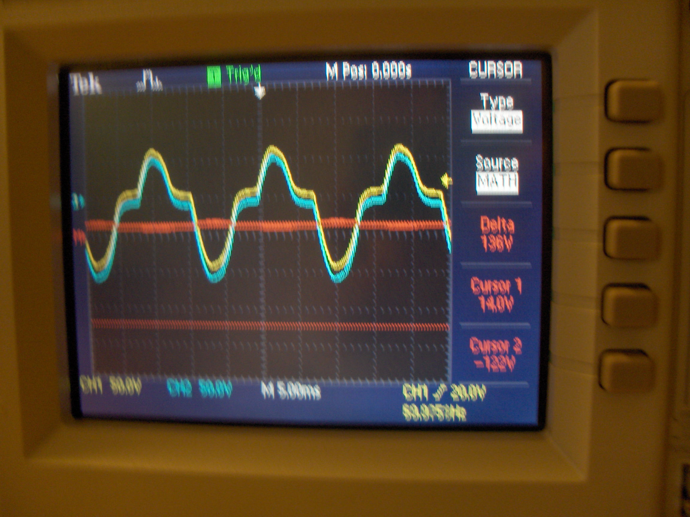
The second picture shows in red what a multi-meter reads. Which the scope reproduces by differencing CH1-CH2. The ripple is a bit better when it has a load but it’s still producing these ridiculously high voltages.
So, it’s producing +12V…sorta. Only as a function of the difference between it’s own +/- reference. Even a good multimeter can be fooled by a bad signal. Normally you’d probably never even notice this because you’d hook your multimeter up to your projects GND which is usually the – on the power supply. If you’d tied this wall warts – to GND, you’d either cook it, or hit it’s current limiter, or both. This little sucker is probably going to be dismantled and tossed.
BEWARE CHEAP WALL-WARTS!