What would you make?
For the few people who actually read this you may or may not know I’m an amateur/hobbyist electronics nerd. I’ve recently gotten back into building custom circuits. I’ve got a couple prototypes on the way and am in a sort of holding pattern until they arrive. One of which I realized I fudged up, but I think I can fix it with some judicious application of green wire.
SO! While I’m waiting for those, I was wondering, by comments, if you could make something what would you make? You never know, I might just throw it together.
Oh and for those wondering what I fudged (and realized that it was fudged like really, just hours after sending it to the PCB house and past the point of no return) it’s a ZIF socket fixture for my STK500 (well or any AVR 10 Pin Programmer) for 28PIN ATMEGA168 compatible DIP parts The next rev will be much better. I forgot to put space for an external oscillator which I use in most of my circuits…the cost of the oscillator and caps is negligible but gives you a much more stable, and if you want faster, clock. Without that you can’t actually program the microcontroller once it’s set to use an external clock.
The other board is going to undergo some serious changes too, but in it’s basic form will probably be used atleast initially as the basis for my own toaster reflow oven for soldering surface mount components (like QFN/MLF bastards with blind thermal pads). It also makes it WAY easier to do SMD’s because you basically put some solder paste on the board, place the parts, then bake them. You just basically touch the solder melting (flow) point for ~45 seconds or so, then let the parts cool.
I do have some ideas, but the ones I’ve got pending will depend on if the oven project is successful or not 🙂 It should be, but the one I’m thinking of will really need surface mount components. So will an improved rev of the controller board for the oven itself, which is actually for a completely different project! 🙂 That’s the beauty of software.
I’ve finally found a relatively cheap place to have boards fabbed up, it just takes ~3 weeks turn-around. But I can have single boards done for around $15 S&H + a cost for their size.
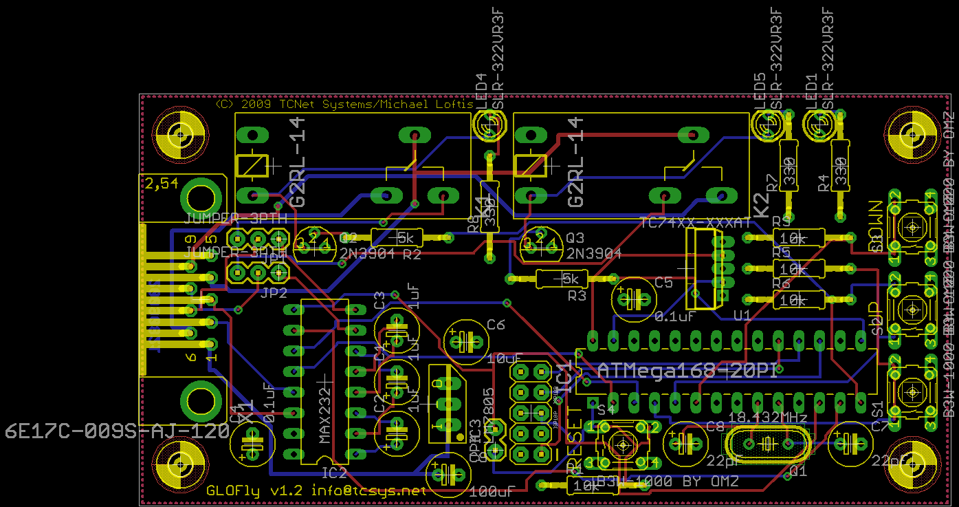
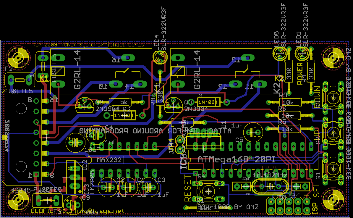
versions 1.2 (sent out for actual prototype) and version 1.3 (in progress) — depending on how well things work out with converting the 1.2 board to a toaster reflow oven…or if i can work out an alternate hot plate system v1.3 will quite probably switch to using SMD’s for the ATMega, the MAX232, most or all of the resistors and capacitors, and probably even the LEDs.
Why is SMD so much better? Well first the parts are smaller, second, if you take a look at those pictures you see that the pins themselves on DIPs are *HUGE* compared to the traces. And each pin/pad punches a hole through your board reducing the space you have to run signals. v1.3 there as you see it took quite a bit of massaging to get everything. v1.2 has a DB-9 (serial) port pictured, v1.3 right now has a Molex part that’s very similar to a PC to motherboard power connector. I’m still debating on exactly what to deploy with that one. Ultimately I want a weather tight connector. The ones I’m looking at now actually mount with a pig tail, but they’re spendy, though they’re fully sealed. Really it probably doesn’t matter as the parts are all pretty hard to kill. The Molex connector causes the problem that I have a hard time getting the bigger traces to it for the relays, so the NO/NC/Center traces for the relays I was manually routing for a bit there…and may end up doing that in the final product too. v1.3 also has three PTC self resetting fuses to protect the board that I omitted in v1.2. I don’t ever plan on letting anyone else get ahold of v1.2, it is 100% prototype, v1.3 though I want to be the first real board. I also set things up so you could make the board (well should be able to) somewhat Arduino compatible, but the oscillator I use is a lot faster than the Arduino sheet’s I’ve seen. I have NO experience with them, but it was a simple hack to put the jumpers in so I could play with it.
For BOTH boards what you’re NOT seeing is the ground plane and +5v plane “fill” polygons of copper. Thats part of what took a lot of tweaking in v1.3 — in v1.2 I didn’t look much at it.
Why? Well…why not?